Preface
This post is my attempt to give an introduction to and overview of building an auto-aim system for RoboMaster. It’s based purely on my own experience, and is essentially just opinion. I am not an expert. I have not personally implemented all of the options I will lay out below. However, I have led implementation of two generations of this system at ARUW, and our 2021-2022 system performed well in competition. Our system runs on the dual-turret sentry, three standard robots, and a hero robot.
These learnings were enabled in huge part by the rest of the ARUW team, including the mechanical and electrical subteams for putting together great robots and other software team members for doing huge amounts of implementation and R&D. I am merely restating the learnings I took away from the whole team’s efforts.
Please do feel free to reply here with questions/comments, edit this post with clarifications, or message on DIscord for further discussion.
We will start by introducing the problem statement and key design archetypes to be considered. I’ll then lay out some practical considerations that I have found to be important and recommendations for how to go about implementing these systems.
The goal of this post is to give a starting point and general advice for system design. I’m not looking to make specific algorithm or technology recommendations, although I’ll mention precedent and historical successes.
What is an auto-aim system?
I will focus specifically on software systems designed to aim and fire at opposing robots’ armor plates. This kind of system is usually implemented using a visual detection mechanism via a camera, and I will assume this going forward.
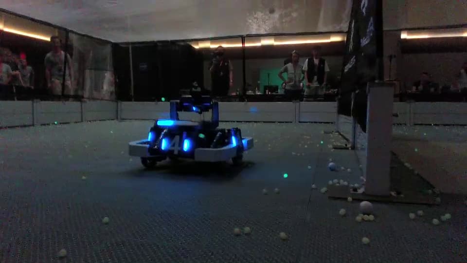
We will assume that we have a robot with two-axis turret (pitch and yaw), a camera mounted on the turret looking “forward”, and some kind of motors which can rotate the axes.
As a first-order approximation, the goal of an auto-aim system is to identify any armor plate of the opposing team’s color and compute the pitch and yaw angles that would point the turret at the target. However, there are many additional layers of complexity. For example, gravity causes projectile droop varying with distance, and fast-moving robots can move a long distance in the time it takes your projectile to fly. We will discuss those toward the end of the post, but keep them in mind throughout.
What we’re not discussing
We will not consider other parts of the game such as:
- Dart guidance
- Rune game
- Robot autonomy
Some of these might be built into/on top of the same “auto-aim” system. However, they are out of scope for this post. (Plus, I+ARUW have never built a successful version of these things, so I am not the right one to tell you about them!)
Inputs and outputs
For the sake of discussion, I will lay out a “standard” set of sensors and controls.
Inputs:
- Camera images. A live camera feed.
- Turret orientation measurements. Perhaps from an encoder or IMU. (Optional)
- Chassis odometry measurements. Estimates of where you are on the field or how fast you are moving. (Optional)
Outputs:
- Motor/turret angles. Probably pitch and yaw. Maybe relative to the chassis, or maybe relative to the “world” using an IMU.
Note: depending on your system architecture, the codebase which does your vision processing might not do all of these things – it could offload some of it to other compute devices. Similarly, it could take on other roles, such as running motor controllers. As we consider various system designs below, it will affect where code might need to go.
Typical high-level topology
Most robots have two computers on them: a “vision processor” and a “controls processor”. This is because RoboMaster robots have to both operate their mechanisms and process images for computer vision. These two tasks tend to have different requirements. The two processors’ attributes are typically as follows. Note that it’s OK if you aren’t familiar with all the terminology here; I provide it only to give more background to those who want it.
- Controls processor
- "Microcontroller-class" CPU.
- Has relatively little compute power, but is very consistent at running small code fast.
- Runs “bare-metal” firmware, where your code is essentially the only thing running.
- Input and output pins which you can use to connect to devices like motors and sensors.
- Bounded scheduling latency. You can e.g. run a loop targeting 1000Hz (loops per second) and be confident it will run exactly that frequently.
- Bounded I/O latency. If your code tries to output a message to a motor, for example, you can be confident that message will be sent as soon as physically possible.
- Very high reliability. Your code will always start on boot, automatically, without fail. Both hardware and software have that one dedicated purpose. You don’t want your robot to be unable to drive because a camera is unplugged or the disk is full!
- Common examples: DJI Development Board (Type A or Type C); other microcontrollers such as Arduino, PJRC Teensy, or STM32 Nucleo.
- Vision processor
- "Application-class" CPU.
- Has enough compute power to do high-volume vision processing. Often has a GPU (Graphics Processing Unit) or other vision accelerator hardware.
- Runs a full operating system (Linux), common desktop computer programs, multiple programs at once.
- More “high-level” ports like USB or Ethernet, for e.g. connecting to a camera.
- Little control over what runs when. The operating system might decide to delay your program by tens of milliseconds (multiple camera frame periods!) if something else needs to use the CPU.
- “Slower” I/O. It might take some time for messages to go in or out.
- Less guaranteed reliability. Your goal is still to have it work 100% of the time, but e.g. it’s your job to configure the operating system to start your program, and it will take tens of seconds to do it. Disconnections and transient failures are harder to track down.
- Common examples: NVIDIA Jetson, DJI Manifold (China). See here for more discussion: Weekly Thread #1: Vision Processing Boards
These two processors have to communicate in some way. Common options are UART and CAN. I won’t go in-depth on these here. However, remember that you will need to write code on both your vision processor and your controls processor to make this communication work.
Which boards, communication methods and tools you use is off-topic for this post. Feel free to start another thread or ask on Discord for more information.
Key design decisions
Key design decision 1: target detection method
An auto-aim system must detect where the target is. Usually, this is done by processing camera images to identify armor plates in the frame. Although this is often the first thing people think of when looking to design an auto-aim system, there is a lot more than just computer vision involved in auto-aim.
There are two primary technological methods that auto-aim systems use to detect targets.
“Classical” computer vision
“Classical” computer vision refers to the family of techniques that have been used in the field since its inception. One designs an algorithm by composing common pixel operations. These operations include:
- Pixel thresholding. For each pixel, you check whether the color value of that pixel is within some range, and set it to either white or black in the output image accordingly.
- Color space conversions. Libraries often tend to operate on pixels in RGB color space, but others exist, such as HSL, HSV, and LAB. Pixel thresholding and other operations might be easier to do in one color space or another.
- Kernel convolutions. You can define elemental filters, such as detecting edges or other shapes, using matrix operations. In the “classical” context, a human designs the kernels manually.
- Binarized erosion and dilation. In essence, filling in gaps or removing small “islands” in a black-and-white image. Often applied after thresholding.
- Blob detection, convex hull estimation, and related algorithms. Often from a binary black-and-white image. Identifying connected chunks of pixels likely making up the “same object”.
All of the algorithms mentioned above have implementations in the popular OpenCV computer vision library, which is extremely powerful and supports pretty much any compute platform.
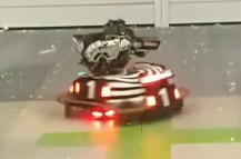
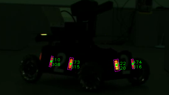
It is important to remember that to detect armor plates it is sufficient to detect the brightly lit red or blue lights on their edges. This means that all you need to do is be able to identify bright red or bright blue lines, and then possibly match them up to figure out which two lines are part of the same plate.
The benefits of classical algorithms include:
- Well-designed algorithms can be very fast if they take advantage of hardware optimizations
- As with above, they can be run using relatively little compute power
- You can design and implement a classical detector in as little as a few hours, and many tutorials for colored object detection exist
- Classical detectors have well-defined behavior; you can figure out exactly what it did and why that happened, and tune the algorithm accordingly
A classical approach’s main drawback is that every edge-case requires custom testing, evaluation, and tuning. It often requires being able to see both armor lights, and you have to be very intentional about calibration and lighting.
I will not give a precise algorithmic design in this post. However, if interested in implementing such a detector I recommend looking up OpenCV tutorials for detecting colored objects, such as tennis balls. There are many out there and they solve a very similar problem.
Classical detectors have been the state-of-the-art of RoboMaster computer vision for as long as the competition has existed. In recent years, the other technique – machine learning – has gained some ground. Nonetheless, I strongly advise against discounting this option too early. While machine learning might be the “cool” tech, it isn’t the easiest way forward nor is it necessarily better.
Machine learning
The reason “classical” computer vision is now considered classic is the emergence of machine learning. In short, ML tackles the algorithmic design problem by requiring that you design only the “shape” of the detection algorithm rather than manually tuning the specific parameters. You either design or find via prior research work a model architecture which people have found performs well for the broad class of tasks, and then “teach it” how to solve your specific problem by showing it examples of what is a correct output.
Usually, the RoboMaster auto-aim detection problem is modeled as an “object detection” task: placing a rectangle around places in the image that contain plates. Many state-of-the-art model architectures look to solve this task. The “YOLO” family is the most prominent.
The major advantage of a machine learning approach is that it can pick up on huge amounts of context from an image that thresholding pixel values cannot. It can infer where plates are while they’re partially blocked by obstacles, learn to reject reflections in shiny walls, and cancel out even extreme motion blur. In exchange, you lose some of the precision one can get with high-resolution pixel-perfect classical detectors.
I won’t go into details on machine learning in this post. However, I caution against eagerly jumping into ML without truly understanding what you’re doing. To successfully implement an ML model, you need:
- Lots of data, including manual labels
- A fairly powerful computer (both for training and for running on-robot)
- An intuition and understanding of the tuning and iteration process of machine learning models
Similarly, it isn’t sufficient to pull a stock YOLO model off the internet and train it on a few RoboMaster images. Even if this model worked well, a typical full-size model is designed for research applications, where they are detecting hundreds of different objects in complex scenarios using GPU hardware that costs more than your tuition. It will not run well on an embedded device like a Jetson. A good starting point is one of the “tiny” YOLO variants.
If I were implementing my first vision system from scratch, I’d probably start with the simplest classical detector that “works”, and then move on to more advanced classical detectors or machine learning once I had something in place.
Key design decision 2: state space and aiming parameters
Yes, those are big words, and I apologize. I promise, they aren’t too bad.
A computer vision detector gives you a point or box in pixel coordinates – i.e., where target(s) are in the image. But how do you aim at it?
This decision will impact both what kind of computation you do on the detected targets, and what the “controls processor” part of your system does with the results. So you’ll have to make sure your decision here jives with the other design decisions you make and components you chose.
Below I’ll describe a handful of archetypes and their advantages and drawbacks. There are lots of additional pieces one can introduce into any of these, and they can be mixed-and-matched. I aim only to survey some of the common options. They are ordered according to increasing complexity.
Design archetype 1: “PID to center” closed loop
This is the simplest approach I have seen. If you suppose your goal is to put the target in the middle of the image, you can implement logic which turns until it’s there. This doesn’t have to be the “true middle”; you could offset it a bit based on where your camera is mounted, compensation for gravity, etc.
Suppose you have picked a single detected target, and computed the its center’s pixel coordinates. A simple approach to aim at the target would be:
- If the target is to the left of the middle of the image, rotate left
- If the target is to the right of the middle of the image, rotate right
- If the target is above the middle of the image, rotate up
- If the target is below the middle of the image, rotate down
I hope it is clear from this description that such an approach is extremely simplistic. You would probably need a “deadzone” in the middle – a point at which it’s “close enough” that you stop trying to move – for this to work at all. It is unlikely it would perform well.
A more practical variant of this approach would achieve the “centering” via the PID (proportional-integral-derivative) controller algorithm. I will leave the design and implementation of PID as an exercise to the reader, using external resources. However, the key is to define your “horizontal error” and “vertical error” as the distance in each dimension of your target from the center, and then use PID to aim in the direction that minimizes that error.
Design archetype 2: Pixel-to-angle extrapolation
This is a common “default” strategy. You estimate how many degrees from the “forward” direction (e.g., image center) your target is, and then send that information to your controls processor. The controls processor uses PID to attempt to rotate the turret’s actual orientation to match the target.
If done naively, this is essentially the same as the previous approach: you’re using PID to minimize the distance from the center. However, it enables some extra “intelligence”. Once you have computed an error angle relative to the middle of the image, you can add this to the current measured turret orientation from your motors or IMU. For example, if your IMU tells you that you’re facing 20 degrees clockwise relative to its compass “zero”, and your vision system computes that the target is 6 degrees counter-clockwise in the image, then your controller would save a target of (20 - 6 = 14) degrees clockwise. You would then use PID to aim in that direction.
The advantage of this approach is that your controls processor can run the PID faster than once per image frame. If, for example, your camera is running at 30 frames-per-second, you receive a frame roughly every 33ms. 33 milliseconds is a long time, and PID controllers work better the more often they are updated. If you only update your controller every 33ms, you’ll often overshoot the target and “oscillate” from one side of the goal to the other. This is a very common mode of error for vision systems. By computing an “absolute” setpoint angle, your controller can update the motor PID as fast as the angle sensor allows; it is able to remember where the target was seen.
Doing the pixel-to-angle conversion depends on the kind of camera used, and can range anywhere from a simple linear extrapolation to a finely-calibrated lens distortion model. This is a topic you may need to research. Relevant terms are “pinhole camera model”, “lens distortion”, and “camera pixel to angle”.
Design archetype 3: Pixel-to-angle extrapolation, but with depth
This variant is very similar to the previous one: compute what angle the target is at relative to your robot or sensors, then aim there. However, it also incoroprates an estimate of distance. Distance is required to accurately compensate for gravity drop or moving robots (time-of-flight).
To compute depth, you can either explicitly measure it via a generic depth sensing technique or estimate it using known plate size. I discuss both options in the next section.
This is the approach that many/most Chinese teams use. They use a camera lens model to estimate position and distance relative to the camera, and then use PID to aim in that direction. It is known to work well, and I strongly recommend looking at Chinese teams’ open-source publications on the topic. However, they tend to have lots of additional processing, filtering and intelligence built on top to make it work well. A key aspect of this is using multiple frames over time to smooth out potentially noisy estimates of where the target is, and introducing estimates of target velocity to be able to “aim ahead” of where the target is moving. You can go very deep with this system design and built a very high-quality auto-aim system.
Estimating depth using known plate size
Many Chinese teams use this approach. They precisely measure the height of each light strip on the plate, and use this to estimate how large the plate itself is, in the image. Using this, the “pixel to angle” method discussed before, and a known size of real plates, you can extrapolate how far away the plate is. You can even use this method for estimating the “pose” of the plate (i.e., where it’s facing).
For information on this approach, the OpenCV library has solid documentation and an excellent implementation used by many teams: OpenCV: Perspective-n-Point (PnP) pose computation
Measuring depth using stereoscopic vision
As humans, we have a very strong understanding of how far away objects are from us. While some of this is due to knowing how large objects are (see above), our primary means of measuring distance is stereoscopic vision, also known computationally as stereo differencing.
In short, we use the difference in perspective between our left and right eyes to estimate how far away a point of reference is. If the object looks very similar from both sides, it’s probably far away; if it is seen in a very different place in each eye, it’s probably close.
As with many of these topics, I won’t attempt to replicate a complete guide to stereo vision here. I recommend doing independent research and following up with any questions. I will discuss the options for implementing stereo vision in practice in the next section.
Design archetype 4: 3D world state
The previous design outline involved tracking what are essentially 3D positions of targets relative to your turret or robot. One of the key extensions to this concept not detailed in this post is how you introduce filtering, velocity estimation and other similar functionality on top of that model. In reality, it is difficult to track the motion of a target relative to your own robot, for one simple reason: your own robot can also move.
To compensate, you can instead track target positions in “world frame”. What world frame means is up to you, but the goal is to remember targets’ locations in a way that isn’t affected by your own robot’s motion. To do this, you must use sensors to attempt to estimate where you are on the field or how you are moving, and adjust your robot-relative measurements accordingly.
This is the design that ARUW uses. We store a set of robots, their plates, and other state in a world-relative coordinate system. We estimate and model their motion to enable high-level reasoning like compensating for spinning robots using timed shots. We track individual robot instances and have a history of where and how they have moved. As far as I know, this is a rare design; most teams, even top Chinese teams, tend to process data in a robot- or turret-relative frame. I can’t say whether it’s better, but our team decided it made sense.
I won’t go into the details of this approach here. Naturally, there are lots of aspects to the design that you’d have to work through and engineer. But hopefully this gives a sense of the range of possible designs.
Key design decision 3: camera and sensing method
Some of the designs we covered above involve additional sensor data beyond a single color image. For example, depth measurements of objects seen in the frame. Similarly, you might have specific requirements on the kind of lens, field of view, maximum frames-per-second, host connectivity (e.g. USB), host software requirements, etc. This post can’t define all possible options or requirements, but I’ll try to give an overview.
Stereo cameras
From a practical standpoint, you can either build your own stereo camera (two separate cameras and a calibration routine, which OpenCV provides) or purchase one such as the Intel RealSense or Stereolabs ZED. Implementing one using your own hardware requires extreme precision, so I do not recommend it for a new team. Meanwhile, pre-made cameras tend to work well but have requirements on the software and hardware environment you connect them to.
Most North American teams use Intel RealSenses. Few to no top Chinese teams do this; they almost all either use the “known plate size” approach or build their own stereo systems.
General camera selections
The below are some recommendations for aspects to look for in a camera.
- 60 frames-per-second or above
- At least 720p resolution
- Solid color settings (ability to configure exposure/white balance/etc. and disable automatic adjustments)
- Easy mounting (talk to your mechanical team)
- Software requirements compatible with your host device – i.e., available drivers and a compatible connector type
- Global shutter. (Not required, but strongly recommended to ensure it works well at moderate-to-high speeds)
So… what hardware do I need?
Your system will need:
- A controls processor (RoboMaster Dev board, other microcontroller)
- A vision processor (e.g. NVIDIA Jetson)
- A communication mechanism between the two. UART is a common choice.
- A camera, probably connected to the vision processor.
- A way of sensing turret orientation (optional)
Remember, all of these components need software to operate them!
Important advice
There’s much more to an auto-aim system than computer vision
In any auto-aim system, there’s a huge amount more to be done than just detecting targets. New teams very often jump immediately to spending their year developing a fancy machine learning target detector, and then show up to competition with nothing else because they thought they could integrate it in a week.
As a rule of thumb, detecting targets is less than 1/3 of the work involved. The rest of the work is processing and filtering the detections, communicating with your controls board, and implementing controls logic to act on your vision. I strongly advise you to plan accordingly. Don’t leave the communication and aiming logic until the end.
Start simple and layer on complexity
A simple system that works is dramatically more useful than an advanced system that doesn’t. If you can deliver an MVP that is very simplistic but successfully aims at a target most of the time at close range, you’ll do well in the North American RM competitions.
Pick technologies that are known to work well
Don’t chase the “cool” tech. Stick to something that’s well-supported and well-understood. I recommend C++, because it is well-supported by libraries like OpenCV and Torch while being faster than Python. ARUW has found that implementing vision systems in Python often leaves you limited by CPU performance and makes it challenging to hit frame rate targets. Python is a perfectly acceptable option if you feel it will be much better, but be aware of the potential performance limitations.
Always Be Recording
ARUW designs all our vision systems to record match footage whenever it’s running. This does have some minor considerations; you want to ensure that you don’t run out of disk space or crash your program due to a video saving issue. However, we have found it extremely valuable to have first-person recordings from our matches. This enables you to test and tune your detector after the competition, diagnose failures, and introduce new training data if you’re using machine learning.
Test in realistic scenarios
It’s really easy to make implicit assumptions that ruin your system in real competition. For example, do you have a way to start your software automatically without human interaction? Do you have a way of telling it which team color it should/shouldn’t shoot? Does the driver’s control interface have a way for them to activate the auto-aim? Does your sentry have a scanning strategy and code to shoot when a target is detected? Do you have a logging mechanism to diagnose failures after a match?
These are questions you must answer before competition. If you don’t, you might as well not have a vision system! Make sure you consider them early. I strongly recommend you start testing in “realistic” conditions – no monitors plugged in, no SSH sessions, etc. – as soon as you can, to ensure that it indeed works like you think it does.
Avenues for research and development
As we’ve touched on, there are lots of ways that this challenge goes beyond “point in the direction of a target”. Some of the big ways things you might need to consider, in descending order of importance, are:
- Gravity. Projectiles droop as they fly. Aiming directly at the plate might not actually hit the target.
- Robots move. As a rule of thumb, a projectile will take a few hundred milliseconds (0.1-0.3 seconds) to hit the target. Robots can move a lot in that time. Aiming on target when you fire doesn’t mean being on target when the projectile arrives.
- Computation latency. It takes time to process an image, and robots may have moved in that time.
- Controller overshoot and oscillation. Sensor latency or insufficiently-tuned controllers can easily turn into uncontrollable aiming oscillations; this is hard to correct for, and sometimes requires an entirely new design for your aiming computations. This is one of the big limitations of the “PID to center” design archetype.
- Your own robot moves. If you are measuring yaw angle relative to “forward” on the chassis, for example, the same target will be at a hugely different angle as your driver rotates the chassis.
- Your robot chassis tilts. If you are aiming using motor encoder angles, i.e. relative to “flat” on the chassis frame, you’ll be very far off target if your robot suspension is tilted by even a few degrees.
- Not all plates are equal, and not all robots are equal. Deciding which plate to aim at isn’t easy.
Some of these have solutions in common, while others each require their own. For example, tracking the velocity of your target will help compensate for latency and compensate for target motion. You will have to consider each of these and iterate on your system. Feel free to reply or start a new thread with questions on these techniques.