In the fall of 2023, I was given a seemingly simple task: Connect to the magnetometer and use its data in our IMUs. Fast-forward a year, and I have now spent countless hours researching IMUs, learning far more theory than I ever wanted to, and reduced our drift by over 90%. At the end of the day… I just ended up throwing money at the problem. Classic.
Context: What’s an IMU
An IMU (Inertial Measurement Unit)is a sensor that tracks rotation and acceleration. Both RoboMaster dev boards come with IMUs built into the board:
- MPU6500 - Built into the Type A board
- BMI088 - Built into the Type C board
Modern IMU fusion algorithms work by integrating angular speed (from the gyroscope) and correcting for drift using gravity as a reference (from the accelerometer). In 2023, ARUW used the Type A board on our chassis and the Type C on our turret.
The MPU6500 was a great IMU…when it released in 2013. It has some pretty terrible cross-axis noise and, due to bugs in our code, had over 100 degrees of drift over the course of a match. The Type C was way better, but putting a whole dev board for just an IMU? A tough ask to our mechanical team.
In the beginning, there was no magnetometer. And then there was. And then were wasn’t again 
Problem: we can’t account for yaw drift with just an accelerometer.
Solution: Magnetometer.
A magnetometer measures magnetic fields and, in theory, can tell you which way is north. Even better, there’s one backed into each development board, the IST8310. In a perfect world, this means we could use it to keep our yaw drift in check.
I got assigned to this around Thanksgiving, which led to 6 weeks of researching what a magnetometer is, learning how to talk to it on the type A board, and taking a board home over winter break to collect some data. The results? Near-zero drift, pog!
And then I put it on a real robot.
Turns out, motors have this really fun physics things called EMI! The moment I turned the motors on, their magnetic fields drowned out the Earth’s field, and my yaw readings shifted by 50 degrees ![]() .
.
No amount of aluminum foil shielding fixed this. The magnetometer was useless. Wahoo!
Why this wasn’t a complete waste of time
Despite that poor showing, I did discover something useful: calibration mattered—a lot.
IMUs on startup don’t report zero motion when static, there is some non-zero bias that you must account for through calibration. Two things affected calibration quality :
- The duration: No surprise, longer was better
- Temperature: IMUs are temperature sensitive. Calibrating before reaching a stable temperature or at a different temperature than the operating condition? Bad data.
Well, guess what we did?
Our calibration process cranked the IMU heater, heating it up by 2 degrees Celsius over the calibration period.
The fix: less than 5 lines
The result: Our drift reduced from 100 degrees to ~5 over the course of a match.
Time taken to find this: 3 months. AAAAAHHHHH
For Taproot teams, taking about 2-4 thousand samples is the sweet spot for us, look at AbstractIMU for the method to change this. In terms of temperature, we found that the Type A stabilizes at around 40 degrees and the Type C at around 25 degrees. As such, we recommend setting temperature targets of 50C and 35C, respectively.
Theory time: Oversampling
With the MPU6500 in a somewhat usable state—and me being somewhat sick of it—I turned to the BMI088.
The BMI088 had built-in functionality for oversampling–taking multiple measurements, averaging them, and reporting a less noisy signal. Due to physics and statistics, this reduces the noise by a factor of \sqrt{\text{measurements}}. A 4x oversample cut noise in half.
Our turret only moved at 30-50hz, so the bandwidth of 96hz offered by a 4x down sample was fine.
For taproot teams, look at setAccOversampling in bmi088
At this point, it was fall of 2024, and I had spent months researching anything that might squeeze out slightly better performance: taking FFTs for optimal low-pass filtering, changing the temperature controller for stability, correcting accelerometer distortions…In the end, either the improvements were too marginal or the implementation was too cumbersome to be worth it. At this point, we had ~5 degrees of drift on the MPU6500 and ~2 degrees of drift on the BMI088.
What if we just bought a better IMU?
After a certain point, I realized that I was just pushing this hardware as far as it could reasonably go. So, what if we just threw money at the problem? Turns out, after all that time, the best solution was to just buy something made in the past 5 years.
After spending some time looking at options, I landed on the ISM330DHCX, a significantly better IMU for $20. Could be even cheaper if you made your own breakout board.
So far our early testing has shown half the noise of the type C. We’ve written a basic I2C driver this past winter and are planning on doing some more comprehensive testing between it and the MPU6500 and BMI088. With any luck, it’ll replace the Type C on our turret. We plan on adding our driver to Taproot sometime this summer, and it’ll likely be a recommended upgrade for HuskyBot. Our current implementation can be found here.
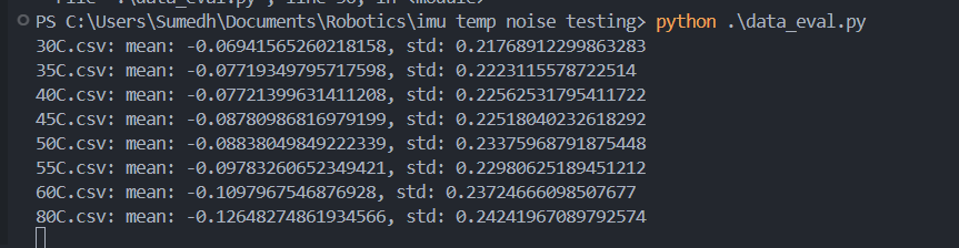
Fun graphs:
The zero-bias offsets and standard deviations in noise as we heat the type C board to various temperatures. Not only is there a shift in bias, but a significant increase in noise as temperature goes up.
Setting a lower range of measurement (125 degrees per second maximum vs 2000 DPS) gives you better granularity ![]() . Trying to set your range to the maximum possible your robot will experience can be a very effective way of reducing noise.
. Trying to set your range to the maximum possible your robot will experience can be a very effective way of reducing noise.
